Electronic Design
Like last week this week also have two assignment one is group assignment and other one is individual assignment.
-
Group assignment:-
use the test equipment in your lab to observe the operation
of a microcontroller circuit board
-
Individual assignment:-
redraw an echo hello-world board,
add (at least) a button and LED (with current-limiting resistor)
check the design rules, make it, and test it
Group Assignment
The Group Assignment page is at the following link.
Electronics Fundamentals
Current (I) is
a flow of electricity which results from the ordered directional movement of electrically charged particles.
Voltage (V), also called electromotive force, is a quantitative expression of the potential
difference in charge between two points in an electrical field. It can be direct or alternating.
Resistance
is an electrical quantity that measures how the device or material reduces the electric current flow through it.
The resistance is measured in units of ohms (Ω). If we make an analogy to water flow in pipes, the resistance is
bigger when the pipe is thinner, so the water flow is decreased.
One volt will drive one coulomb (6.24 x 10¹⁸)
charge carriers, such as electrons, through a resistance of one ohm in one second.
Kirchhoff's current
law
The principle of conservation of electric charge implies that:
At any node (junction) in an electrical circuit,
the sum of currents flowing into that node is equal to the sum of currents flowing out of that node.
The algebraic equation for the following diagram would look like, i2 + i3 = i1 + i4
Ohm's Law
Ohm's law states that the current through a conductor between two points
is directly proportional to the voltage across the two points. Introducing the constant of proportionality, the resistance;
 where
where
I is the current through the conductor in units of amperes,
V is the voltage measured across the conductor in units of volts, and
R is the resistance of the conductor in units of ohms.
Faraday's
Law
The induced electromotive force in any closed circuit is equal to the negative of the time
rate of change of the magnetic flux enclosed by the circuit.

where ℰ is
the electromotive force (EMF) and ΦB is the magnetic flux.
Electronic Components
Active and Passive components
Active electronic
components are those that can control the flow of electricity. Some examples of active electronic components are transistors,
vacuum tubes, silicon-controlled rectifiers.
Passive electronic components are those that don’t have the ability
to control current by means of another electrical signal. Examples of passive electronic components are capacitors, resistors, inductors.
Transistors
A transistor is a device that regulates current or voltage flow and acts as a switch or gate for electronic signals. Transistors consist of three layers of a semiconductor material, each capable of carrying a current. A voltage or current applied to one pair of the transistor's terminals controls the current through another pair of terminals. Because the controlled
(output) power can be higher than the controlling (input) power, a transistor can amplify a signal.
Operational
Amplifier
An operational amplifier (often op-amp or opamp)
is a DC-coupled high-gain electronic voltage amplifier with a differential input and, usually, a single-ended output. In this
configuration, an op-amp produces an output potential (relative to circuit ground) that is typically hundreds of thousands of times
larger than the potential difference between its input terminals. Wiki Link.
Pull-up / down Resistors
With a pull-up resistor, the input pin will read a high state when the button is not pressed. In other words, a small amount of current is flowing between VCC and the input pin (not to ground),
thus the input pin reads close to VCC. When the button is pressed, it connects the input pin directly to ground.
A pull-down
resistor works in the same way but is connected to ground. It holds the logic signal near zero volts when no other active device is
connected. The value of a pull down or pull up resistor will vary depending upon your specific devices involved.
Filter
Capacitor
A filter capacitor is a capacitor which filters out a certain frequency or range of frequencies from a circuit.
Usually capacitors filter out very low frequency signals. These are signals that are very close to 0Hz in frequency value.
These are also referred to as DC signals. When for some reason voltage drops,
capacitor acts to stabilize the voltage. Capacitor doesn't allow sudden change in voltage.
Inductor
Inductor is a passive two-terminal
electrical component that stores electrical energy in a magnetic field when electric current is flowing through it.
An inductor is characterized by its inductance, which is the ratio of the voltage to the rate of change of current.
Microprocessors and Microcontrollers
A microprocessor
generally does not have RAM, ROM and IO pins. It usually uses its pins as a bus to interface to peripherals such as
RAM, ROM, Serial ports, Digital and Analog IO. It is expandable at the board level due to this.
A microcontroller
is 'all in one', the processor, ram, IO all on the one chip, as such you cannot (say) increase the amount of
RAM available or the number of IO ports. The controlling bus is internal and not available to the board designer.
This means that a microprocessor is generally capable of being built into bigger general purpose applications than a microcontroller.
The microcontroller is usually used for more dedicated applications.
Know more about Microcontroller Architecture.
Datasheet for ATTINY44A-SSU-ND
Schematic designing
I have started this week by downloading Eagle software from Autodesk which licence has given by
fab academy. Although I have an little experience with kicad. I chose to work with Eagle software Also,
I chose it because I would like to learn about different and new PCB designing tools. I have started by watching a
youtube video to learn how to install libraries, add parts, connect wires and edit schematic layout in Eagle.The video was really helpful
and I get familiar with the software very fast. Here are the steps I followed to design my circuit of this week.
Autodesk Eagle
EAGLE is a scriptable electronic design automation (EDA) application with schematic capture, printed circuit board (PCB) layout, auto-router and computer-aided manufacturing (CAM) features. EAGLE stands for Easily Applicable Graphical Layout Editor.
EAGLE contains a schematic editor, for designing circuit diagrams. Schematics are stored in files with .SCH extension, parts are defined in device libraries with .LBR extension. Parts can be placed on many sheets and connected together through ports.
The PCB layout editor stores board files with the extension .BRD. It allows back-annotation to the schematic and auto-routing to automatically connect traces based on the connections defined in the schematic.
EAGLE saves Gerber and PostScript layout files as well as Excellon and Sieb & Meyer drill files. These are standard file formats accepted by PCB fabrication companies, but given EAGLE's typical user base of small design firms and hobbyists, many PCB fabricators and assembly shops also accept EAGLE board files (with extension .BRD) directly to export optimized production files and pick-and-place data themselves.
EAGLE provides a multi-window graphical user interface and menu system for editing, project management and to customize the interface and design parameters. The system can be controlled via mouse, keyboard hotkeys or by entering specific commands at an embedded command line. Multiple repeating commands can be combined into script files (with file extension .SCR). It is also possible to explore design files utilizing an EAGLE-specific object-oriented programming language (with extension .ULP).
Autodesk Eagle is compatible in Windows, IOS and Linux.
FAB Library
FAB library contains the design of the various SMD conponents that are available in our FABLAB, And we have to load this FAB library into the software.
First I had to download the FAB library from our the gitlab FAB cloud.

Tapas@tapas-HP-G5-SFF:~/Downloads/Autodesk_EAGLE_9.6.2_English_Linux_64bit/eagle-9.6.2$ ls -l
total 21680
drwxr-x--- 3 tapas tapas 4096 May 20 2020 bin
drwxr-x--- 3 tapas tapas 4096 May 20 2020 cache
drwxr-x--- 3 tapas tapas 4096 May 20 2020 doc
-rwxr-x--- 1 tapas tapas 22150216 May 20 2020 eagle
drwxr-x--- 9 tapas tapas 4096 May 20 2020 examples
drwxr-x--- 2 tapas tapas 4096 May 20 2020 lib
drwxr-x--- 2 tapas tapas 4096 May 20 2020 libexec
tapas@tapas-HP-G5-SFF:~/Downloads/Autodesk_EAGLE_9.6.2_English_Linux_64bit/eagle-9.6.2$ ./eagle run
./eagle: symbol lookup error: /lib/x86_64-linux-gnu/libGLX_mesa.so.0: undefined symbol: xcb_dri3_get_supported_modifiers
tapas@tapas-HP-G5-SFF:~/Downloads/Autodesk_EAGLE_9.6.2_English_Linux_64bit/eagle-9.6.2$ sudo ./eagle run
[sudo] password for tapas:
QStandardPaths: XDG_RUNTIME_DIR not set, defaulting to '/tmp/runtime-root'
./eagle: symbol lookup error: /lib/x86_64-linux-gnu/libGLX_mesa.so.0: undefined symbol: xcb_dri3_get_supported_modifiers
tapas@tapas-HP-G5-SFF:~/Downloads/Autodesk_EAGLE_9.6.2_English_Linux_64bit
tapas@tapas-HP-G5-SFF:~/Downloads/Autodesk_EAGLE_9.6.2_English_Linux_64bit/eagle-9.6
tapas@tapas-HP-G5-SFF:~/Downloads/Autodesk_EAGLE_9.6.2_English_Linux_64bit/eagle-9.6.2$ cd lib
tapas@tapas-HP-G5-SFF:~/Downloads/Autodesk_EAGLE_9.6.2_English_Linux_64bit/eagle-9.6.2/lib$ ls -l
total 189196
-rwxr-xr-x 1 tapas tapas 78424 May 20 2020 libavahi-client.so.3
issue resolve
Environment:
Linux
Solution:
Follow these steps:
-
Open Terminal;
-
Move to the directory .../eagle-9.6.2/lib;
-
Run the command rm libxcb*;
-
Launch Eagle.

As i was installed in ubuntu then i run Open Terminal and run the ./eagle run once open the eagle interface then click file then
new then click on Project;
update the libraries
Under the new project,click file and Schematic

Select library and go to library manager

At library manager browse the fab library downloaded file and upload it to eagle and update

Now the new FAB library get loaded to the Eagle software.

Here i have already updated of fab libraries for my design

PCB designing;
Launch Eagle.
For the Echo Hello World board, I started with
Eagle to create the schematic drawing for the same. as follow in the academy.cba.mit.edu


Selected the ATTiny thats available at our FabLab, ATTINY44-SSU, from fab.ldr and similarly selected all the components I wanted to
recreate the Echo Hello World board. I used the following image to recreate my schematic diagram. The next screenshot is the one I created.
The commands I used were net, delete, show, move
I used the FAB library SMD components.
I inserted all the required SMD components for my circuit into the schematic design page.
I then added all the required SMD componenets.
1) VCC
2) GND
3) Resistor
4) Capacitor
5) ATtint44
6) FTDI
7) ISP
8) LED
9) Tactile switch

I made the connection using the 'Line' tool and 'Name' tool.
But in the assignment
requires me to connect an LED and a push button, I updated the schematic diagram accommodating both.
The component can be moved, rotated and mirrored by clicking on the following icons from the tool bar,
 then click on the component itself.
Name the pins by typing name in the command line. Change the name to the desired(here VCC) in the popup. 
Once all pins are connected, my final Schematic diagram looked like this.

Check for errors using ERC button  in the tool bar.
The output of my ERC check:

I found the resistance value
of the current limiting resistor for the LED. I used the datasheet to find the voltage (1.8 V), the test current (10 mA). The resistance was found to be 330 ohms but since our
FabLab doesnt have that kind of resistor, I had to use the 499 ohm resistor.
After completing the schematic design, I saved it and moved to the board design.


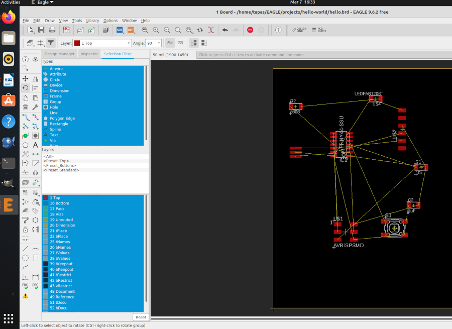
I then placed
the components away from each other and checked whether the airwires cross each other. I rotated and moved the
components so that there is minimum crossing of airwires.
As per the default setting the widths are set to 6mil.
This thickness cannot be achieved using our Milling machine.
The design rule can be changed from the 'Design Rule' in the 'Edit' option on the taskbar.

As per the default setting the widths are set to 6mil.
I used the auto-route feature to create my layout the first time.Following are the result but its not fruitful


I decided to manually redraw the connections and layouts. The problem with most
of these trial not working out is that there will be at least one intersection happening

Once you are done with your board layout. You can do the following commands:
- “ratsnest”, to compile the design.
- “display none top”, this will display just the top layer (copper and traces layer).
- “export image”, this will enable you to export as .png. Select Monochrome and 1000 dpi.
- “display none dim”. this will display just the dimension layer which is the outline.
- “export image”, same setting but different name (eg. outline.png).
To export the file design as
png file, Go to 'FILE' on the taskbar and click 'EXPORT' and select
'IMAGE'. Then a window opens and browse the destination,
make it monochrome and change the resolution to 1000dpi.

After obtaining the Outline export the file as png as the same way we exported the the traces.
The TRACES and the OUTLINE for milling.


After milling the PCB.Required component for soldering the circuit.


For testing the "Hello Echo board" I connected it to the computer using the "USBATtinyISP micro-controller" made during Electronics Production week.
Make sure that the ground (GND) of both the boards are connected to each other.

I am very new to the Arduino just i have tried little.

Click to download the files :
Group assignment:-
Individual assignment:-
Voltage (V), also called electromotive force, is a quantitative expression of the potential difference in charge between two points in an electrical field. It can be direct or alternating.
Resistance is an electrical quantity that measures how the device or material reduces the electric current flow through it. The resistance is measured in units of ohms (Ω). If we make an analogy to water flow in pipes, the resistance is bigger when the pipe is thinner, so the water flow is decreased.
One volt will drive one coulomb (6.24 x 10¹⁸) charge carriers, such as electrons, through a resistance of one ohm in one second.
Kirchhoff's current law
The principle of conservation of electric charge implies that:
At any node (junction) in an electrical circuit, the sum of currents flowing into that node is equal to the sum of currents flowing out of that node. The algebraic equation for the following diagram would look like, i2 + i3 = i1 + i4
Ohm's law states that the current through a conductor between two points is directly proportional to the voltage across the two points. Introducing the constant of proportionality, the resistance;
whereI is the current through the conductor in units of amperes,
V is the voltage measured across the conductor in units of volts, and
R is the resistance of the conductor in units of ohms.
The induced electromotive force in any closed circuit is equal to the negative of the time rate of change of the magnetic flux enclosed by the circuit.
where ℰ is the electromotive force (EMF) and ΦB is the magnetic flux.
Active electronic components are those that can control the flow of electricity. Some examples of active electronic components are transistors, vacuum tubes, silicon-controlled rectifiers.
Passive electronic components are those that don’t have the ability to control current by means of another electrical signal. Examples of passive electronic components are capacitors, resistors, inductors.
Transistors
A transistor is a device that regulates current or voltage flow and acts as a switch or gate for electronic signals. Transistors consist of three layers of a semiconductor material, each capable of carrying a current. A voltage or current applied to one pair of the transistor's terminals controls the current through another pair of terminals. Because the controlled (output) power can be higher than the controlling (input) power, a transistor can amplify a signal.
An operational amplifier (often op-amp or opamp) is a DC-coupled high-gain electronic voltage amplifier with a differential input and, usually, a single-ended output. In this configuration, an op-amp produces an output potential (relative to circuit ground) that is typically hundreds of thousands of times larger than the potential difference between its input terminals. Wiki Link.
Pull-up / down Resistors
With a pull-up resistor, the input pin will read a high state when the button is not pressed. In other words, a small amount of current is flowing between VCC and the input pin (not to ground), thus the input pin reads close to VCC. When the button is pressed, it connects the input pin directly to ground.
Filter Capacitor
A filter capacitor is a capacitor which filters out a certain frequency or range of frequencies from a circuit. Usually capacitors filter out very low frequency signals. These are signals that are very close to 0Hz in frequency value. These are also referred to as DC signals. When for some reason voltage drops, capacitor acts to stabilize the voltage. Capacitor doesn't allow sudden change in voltage.
Inductor is a passive two-terminal electrical component that stores electrical energy in a magnetic field when electric current is flowing through it. An inductor is characterized by its inductance, which is the ratio of the voltage to the rate of change of current.
Microprocessors and Microcontrollers
A microprocessor generally does not have RAM, ROM and IO pins. It usually uses its pins as a bus to interface to peripherals such as RAM, ROM, Serial ports, Digital and Analog IO. It is expandable at the board level due to this.
A microcontroller is 'all in one', the processor, ram, IO all on the one chip, as such you cannot (say) increase the amount of RAM available or the number of IO ports. The controlling bus is internal and not available to the board designer.
This means that a microprocessor is generally capable of being built into bigger general purpose applications than a microcontroller. The microcontroller is usually used for more dedicated applications.
Linux
Solution:
Follow these steps:Under the new project,click file and Schematic
Select library and go to library manager
At library manager browse the fab library downloaded file and upload it to eagle and update
Now the new FAB library get loaded to the Eagle software.
Here i have already updated of fab libraries for my design
1) VCC
2) GND
3) Resistor
4) Capacitor
5) ATtint44
6) FTDI
7) ISP
8) LED
9) Tactile switch
then click on the component itself.